Table of Contents
Field of View (FOV)
From our last blog, we learned that to perform perspective projection, we need to define the frustum's boundaries: left, right, bottom, top, far, and near. For a camera, the Field of View (FOV) is crucial as it defines the width of the viewable area. In computer graphics, we utilize the fov-Y and the Aspect Ratio, where the aspect ratio is the width divided by the height.
Assuming symmetry:
Canonical Cube to Screen
After applying Model transformation (placement of objects), View transformation (placement of the camera), and Projection transformation (Orthographic and Perspective Projection), we need to map the Canonical Cube () to screen. This process involves placing an object into a 2D array of pixels. A Pixel, short for Picture Element, can be considered as a uniformly sized little square.
Rasterization is the process of drawing onto screen pixels.
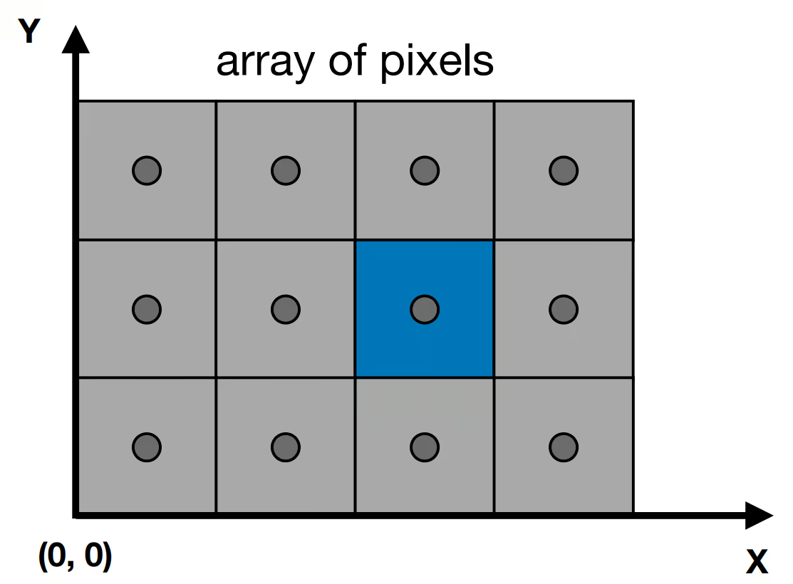
Here, we define coordinates starting from the left bottom corner. The Pixel locate at and , start with zero.
What we do now is transform our canonical cube to screen using matrix:
Triangles
We can decompose any polygon into a mesh of triangles. Triangles offer numerous benefits:
- Planar
- Well-defined interior
- Easy to do interpolation
Now, assume we have a triangle, and we know the coordinates of its corners after the transformations. How do we determine what our pixel should look like, especially at the edge of the triangle?
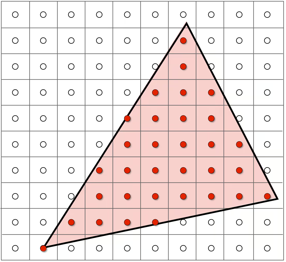
Sampling
We evaluate the triangle signal at our pixel, thus discretizing it.
Assume sampling at the centre of the pixel:
use rayon::prelude::*;

fn main() {
    let x_max = 1024;
    let y_max = 768;
    let mut image = vec![vec![false; y_max]; x_max];

    // assume triangle
    let triangle = [(0, 0), (1024, 0), (512, 768)];

    // AABB
    let min_x = triangle.iter().min_by_key(|v| v.0).unwrap().0;
    let max_x = triangle.iter().max_by_key(|v| v.0).unwrap().0;
    let min_y = triangle.iter().min_by_key(|v| v.1).unwrap().1;
    let max_y = triangle.iter().max_by_key(|v| v.1).unwrap().1;

    // pre-calc edge
    let edges = [
      (triangle[1].0 - triangle[0].0, triangle[1].1 - triangle[0].1),
      (triangle[2].0 - triangle[1].0, triangle[2].1 - triangle[1].1),
      (triangle[0].0 - triangle[2].0, triangle[0].1 - triangle[2].1),
    ];

    (min_x..=max_x).par_iter_mut().enumerate().for_each(|(x, row)| {
        for y in min_y..=max_y {
            image[x as usize][y as usize]= is_inside(&triangle, x as usize, y as usize);
        }
    });
}

fn is_inside(edges: &[(i32,i32);3],triangle: &[(i32, i32); 3], p:(usize,usize) -> bool {
   // p to edge
    let to_p = [
        (p.0 - triangle[0].0, p.1 - triangle[0].1),
        (p.0 - triangle[1].0, p.1 - triangle[1].1),
        (p.0 - triangle[2].0, p.1 - triangle[2].1),
    ];

    let cross = [
        edges[0].0 * to_p[0].1 - edges[0].1 * to_p[0].0,
        edges[1].0 * to_p[1].1 - edges[1].1 * to_p[1].0,
        edges[2].0 * to_p[2].1 - edges[2].1 * to_p[2].0,
    ];

    // if same sign, means inside
     cross[0].signum() == cross[1].signum() && cross[1].signum() == cross[2].signum()
}
This approach may cause aliasing, due to our sampling rate not being high enough for our signal.