Table of Contents
Goal
Our goal is to create a simple GUI program that displays a triangle through a very simple soft raster. And we need to implement the ability to control the rotation of the triangle around a certain axis by pressing the A or D keys by modifying the transformation matrix.
GUI
First, as we do in Post CG-01, we build a simple GUI to handle our practice.
We still use winit and this time, we want to build render by ourself, so no OpenGL involved.
We use a event_loop to monitor all keyboard events and use that to operate our program.
fn main() {
    let size = LogicalSize::new(640,480);
    let event_loop = EventLoop::new().unwrap();
    let builder = WindowBuilder::new();

    event_loop.set_control_flow(ControlFlow::Wait);

    let window = builder
        .with_title("My Image Viewer")
        .with_inner_size(size)
        .build(&event_loop)
        .unwrap();

    event_loop
        .run(move |event, elwt| match event {
            Event::WindowEvent {
                event: WindowEvent::CloseRequested,
                ..
            } => {
                println!("The close button was pressed; stopping");
                elwt.exit();
            }
            Event::WindowEvent {
                event:
                    WindowEvent::KeyboardInput {
                        event:
                            KeyEvent {
                                physical_key: PhysicalKey::Code(keycode),
                                state: ElementState::Pressed,
                                ..
                            },
                        ..
                    },
                ..
            } => match keycode {
                KeyCode::KeyA  =>{
                    println!("A key was pressed");
                },
                KeyCode::KeyD => {
                    println!("D key was pressed");
                },

                KeyCode::Escape => {
                    println!("The ESC button was pressed; stopping");
                    elwt.exit();
                }
                _ => (),
            }
            }
            _ => (),
        })
        .unwrap();
}
This framework shows a blank window, and we can press A,D and ESC to toggle some events.
When we press A,D,Esc, it will print some information. Later we will change it to commands of our rendering program.
A key was pressed
D key was pressed
A key was pressed
D key was pressed
The ESC button was pressed; stopping
Drawing Space
Now, since we don't have OpenGL or some rendering stack. We need something similar to simulate our screen.
Here I use Pixels. It is a tiny hardware-accelerated pixel frame buffer. We can render our stuff and write into that buffer, to simulate our screen.
We can create a simulated pixel screen by just assigning the size. Then we shall have a simple buffer.
    let window_size = window.inner_size();
    let surface_texture = SurfaceTexture::new(window_size.width, window_size.height, &window);
    let mut pixels = Pixels::new(window_size.width, window_size.height, surface_texture).unwrap();
Next, lets draw something on the screen. We will need a rasterizer to handle all the drawing, so we can start with a naïve implement of rasterizer.
pub struct Rasterizer {

}

impl Rasterizer {
    pub fn new() -> Self {
        Rasterizer{}
    }

    pub fn draw(&self,frame:&mut [u8],width:u32,height:u32,a_or_d:bool)
    {
        for (i,pixel) in frame.chunks_exact_mut(4).enumerate() {
            let x = (i % width as usize) as i16;
            let y = (i / width as usize) as i16;

            let rgba = if a_or_d {
                [0x5e, 0x48, 0xe8, 0xff]
            } else {
                [0x48, 0xb2, 0xe8, 0xff]
            };

            pixel.copy_from_slice(&rgba)
        }
    }
}
As you see, this is just a frame work of Rasterizer, we defined a simple draw, which accept a &mut [u8] buffer as input, then based on our type "A" or "D" to draw different color on the screen.
Then back to our main function, add simple logic to control the drawing.
                KeyCode::KeyA  =>{
                    println!("A key was pressed");
                    a_or_d = !a_or_d;
                    window.request_redraw();
                },
                KeyCode::KeyD => {
                    println!("D key was pressed");
                    a_or_d = !a_or_d;
                    window.request_redraw();
                },

            Event::WindowEvent {
                event: WindowEvent::RedrawRequested,
                ..
            } =>{
                rasterizer.draw(pixels.frame_mut(), window_size.width, window_size.height, a_or_d);
                pixels.render().unwrap();
            },
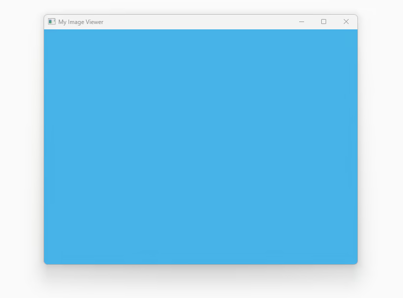
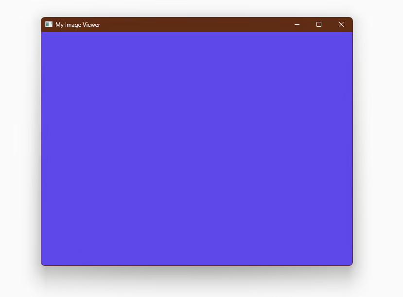
Now we we press the key "A" or "D", a bool will flip, and request redraw. In RedrawRequested arm our rasterizer will took pixels' buffer and redraw color based on a_or_d.
When we press A or D, the color of window will change.
Triangle
We can easily set up a simple triangle class to manage our object. Our focus is solely on wireframe rendering, which means we are concerned with the edges of the triangle. So our goal is to simply transform our input edges to Vec4 orthographic coordinates.
pub struct Triangle {
    vertices: [Vec3; 3],
}
impl Triangle {
    pub fn new(vertices: [Vec3; 3]) -> Self {
        Self { vertices }
    }

    pub fn to_vertices(&self) -> Vec<Vec4> {
            self.vertices.iter().map(|v| {
                Vec4::new(v.x, v.y, v.z, 1.0)
            }).collect()
    }
}
Here, we define only one method that transforms an input Vec3 array into a Vec4 vector.
Rasterizer
Next, we will implement several transformation matrices in the rasterizer.
Model Matrix
The first is the model transformation matrix. This matrix controls the movement and positioning of the target object.
Because our objective is to make the object rotate around a random axis, we will construct a rotation matrix using Rodrigues' rotation formula: where is an identity matrix, and is a cross product of axis .
// this should do the same work with glm::rotate()
pub fn set_model(&mut self, rot_axis: &Vec3, rot_angle: f32) {
    let norm_axis = rot_axis.normalize();
    let cos_theta = rot_angle.cos();
    let sin_theta = rot_angle.sin();

    // identity
    let i = Mat4::identity();
    // cross product matrix
    let k = Mat4::new(
            0f32        , -norm_axis.z, norm_axis.y , 0f32,
            norm_axis.z , 0f32        , -norm_axis.x, 0f32,
            -norm_axis.y, norm_axis.x , 0f32        , 0f32,
            0f32        , 0f32        , 0f32        , 0f32,
        );
	 // R
	self.model = i + k * sin_theta + k * k * (1f32 - cos_theta);
}
Now, our set_model function can accept an axis, which is a Vec3, and a rotation angle, specified in radians as an f32, to generate a Mat4 rotation matrix.
View Matrix
Next is the view matrix, which determines how we set up our camera. After multiplication with this matrix, the object will be moved into the camera's world, where our camera is positioned at the centre and oriented towards the negative z-axis. Therefore, this matrix is also referred to as the "look-at" matrix.
// as same as glm::look_at
fn set_view(&mut self,eye:&Vec3,center:&Vec3,up:&Vec3) {
    let f = (center - eye).normalize();
    let r = f.cross(&up.normalize()).normalize();
    let u = r.cross(&f);

    self.view = Mat4::new(
        r.x         , u.x         , -f.x       , 0f32,
        r.y         , u.y         , -f.y       , 0f32,
        r.z         , u.z         , -f.z       , 0f32,
        -r.dot(&eye), -u.dot(&eye), f.dot(&eye), 1f32,
    )
}
Here, we use eye to represent the camera's position, center as the target we are looking at, and up as the upward direction. First, we calculate the forward and side unit vectors. Then, we recalculate the up vector through a cross product to ensure the up and side directions are orthogonal.
Please note that we add a negative sign to the forward vector to ensure it is oriented towards the negative z-axis.
Projection Matrix
The next matrix is the projection matrix, for which we use perspective projection. It requires the aspect ratio, which is the width divided by the height of the camera space, fovY, the vertical field of view in radians, and the near and far plane coordinates.
// set projection
pub fn set_projection(&mut self, aspect: f32, fovy: f32, near: f32, far: f32) {
    let f = 1.0 / (fovy / 2.0).tan();
    self.projection = Mat4::new(
        f/aspect, 0f32, 0f32                            , 0f32 ,
        0f32    , f   , 0f32                            , 0f32 ,
        0f32    , 0f32, -(far + near) / (far - near)    , -1f32,
        0f32    , 0f32, -2.0 * far * near / (far - near), 0f32 ,
    )
 }
Viewport Matrix
The final transformation is the viewport transform. After the previous three transformations, the object is transformed into a space. We then need to map this space onto the screen.
pub fn set_viewport(&mut self, width: f32, height: f32, near: f32, far: f32) {
    let width_half = width / 2f32;
    let height_half = height / 2f32;
    let near_half = near / 2f32;
    let far_half = far / 2f32;
    self.viewport = Mat4::new(
            width_half, 0f32        , 0f32                , width_half          ,
            0f32      , -height_half, 0f32                , height_half         ,
            0f32      , 0f32        , far_half - near_half, far_half + near_half,
            0f32      , 0f32        , 0f32                , 1f32                ,
    )
}
Wireframe
Before implementing the entire drawing process, there's one last part we need to address. Our previous transformations only affect the edges of the triangle, but we need to display the entire object on the screen. Therefore, we will implement wireframe drawing. As discussed in the last post, we will sample the wireframe using the Bresenham algorithm.
fn draw_line_bresenham(
    &mut self,
    point1: Vec4,     // start
    point2: Vec4,     // end
    frame: &mut [u8], // buffer
    width: usize,
    color: [u8; 4], // RGBA
) {
    let x1 = (point1.x / point1.w).round() as i32;
    let y1 = (point1.y / point1.w).round() as i32;
    let x2 = (point2.x / point2.w).round() as i32;
    let y2 = (point2.y / point2.w).round() as i32;

    let dx = (x2 - x1).abs();
    let dy = -(y2 - y1).abs();
    let sx = if x1 < x2 { 1 } else { -1 };
    let sy = if y1 < y2 { 1 } else { -1 };

    let mut x = x1;
    let mut y = y1;

    let mut err = dx + dy;

    loop {
        if x >= 0 && y >= 0 && (x as usize) < width && (y as usize * width) < frame.len() / 4 {
            let idx = (x as usize + y as usize * width) * 4;
            for (i, color_value) in color.iter().enumerate() {
                frame[idx + i] = *color_value;
            }
        }
        if x == x2 && y == y2 {
            break;
        }
        let e2 = 2 * err;
        if e2 >= dy {
            err += dy;
            x += sx;
        }
        if e2 <= dx {
            err += dx;
            y += sy;
        }
    }
}
This function takes two points and a frame buffer as inputs and draws the line in a specified color.
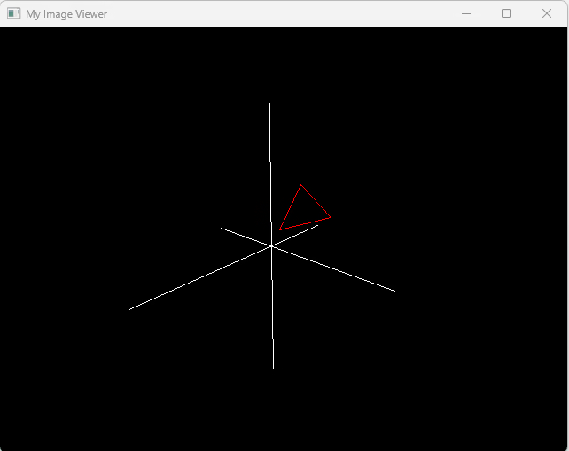
Drawing
Finally, we can implement our drawing process. We take a pair of points and the index of a triangle. For each point, we apply our MVP (Model, View, Projection) matrix to convert the point into orthogonal space. Then, we apply the viewport transform to convert it into screen coordinates. After this, we can use the Bresenham algorithm to draw the line.
pub fn draw(&mut self, frame: &mut [u8], width: u32, vertices: &[Vec4], indices: &[usize]) {
    self.clear_buffer(frame, [0, 0, 0, 255]);

    // mvp and viewport
    let vertices: Vec<Vec4> = vertices
        .iter()
        .map(|vertex| {
            let vertex = self.mvp_transform(&vertex);
            self.viewport_transform(&vertex)
        })
        .collect();

    for i in 0..indices.len() {
        let p1 = vertices[indices[i]]; // current
        let p2 = vertices[indices[(i + 1) % indices.len()]]; // next, loop

        self.draw_line_bresenham(p1, p2, frame, width as usize, [255, 0, 0, 255]);// draw red line
    }
}
Then, we are done. In our GUI, we modify the behavior of the A and D keys. Upon pressing a key, we call set_view() to change the view matrix, and then request a redraw. As a result, we should see the object rotating on the screen.